Small, Simple and Serviceable - these were the leading principles guiding the Electrical architecture of the Mini-AUV. The product is a two PCB system which handles the entire power and signal network of the AUV.
Architectural Overview
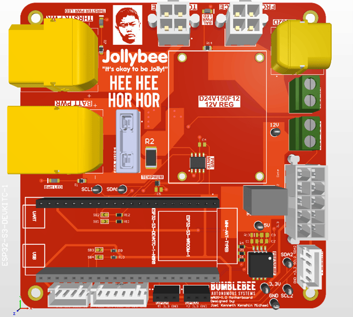
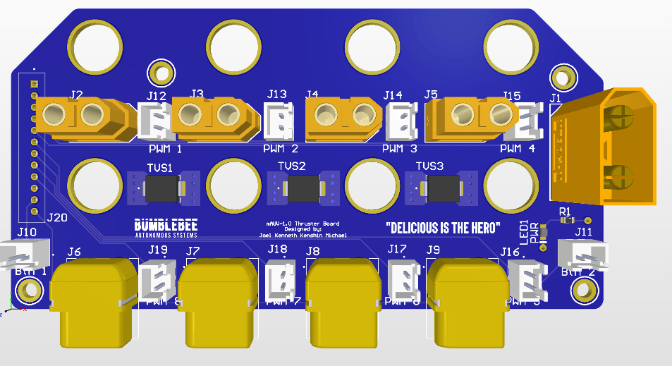
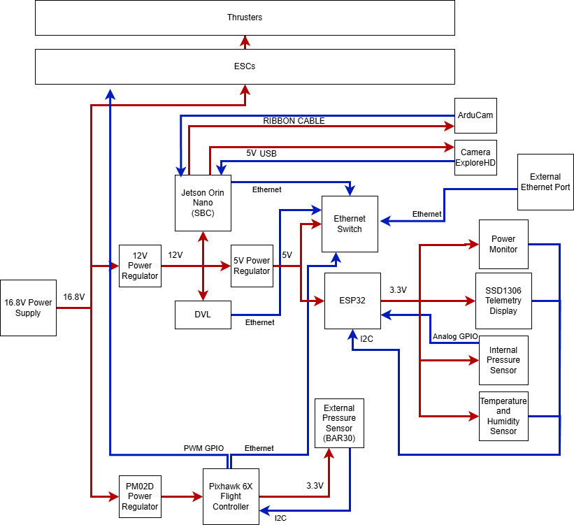
We decided on trying out a typical drone technology stack, involving the use of a Pixhawk, to emulate the lightweight nature of their electrical architecture. The end result is a simple system that offers stable hardware for the software to shine. The Thruster PCB hosts and manages the signals and power of eight Blue Robotics ESCs, as well as kill switch and button signals sent from the thruster endcap. The motherboard PCB contains its own power monitoring capabilities, alongside temperature, humidity and pressure sensors managed by an ESP32 Development Kit—all displayed on a small telemetry screen. The Pixhawk holds the IMU sensor stack and interfaces with the Blue Robotics Bar30 external pressure sensor via I2C. In addition, an Ethernet switch is used to communicate with the compute unit.
Easy Access
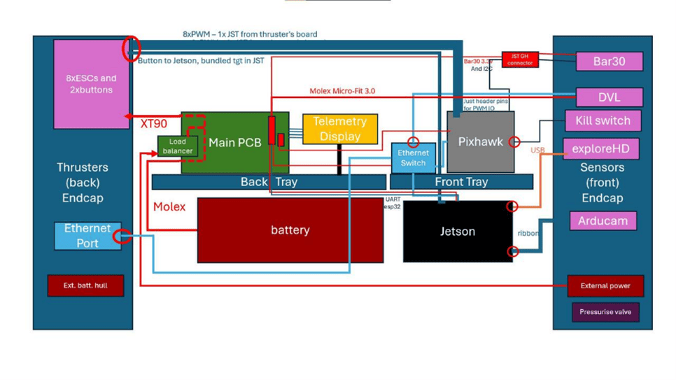
Accessing and maintaining the Mini-AUV is as easy as 1-2-3. The electrical architecture fits within three key operational goals that interface with each other through a neat series of JST and Molex connections. The subteam worked closely with the mechanical subteam to ensure that the cables to the end-cap PCB can be easily disconnected to enable quick access to the internals.