This year, we have focused on re-inventing our software controls. We have developed a new velocity-based controller which allows our AUV to manoeuvre at higher speeds while maintaining precise control to complete the various manipulation challenges.
At the highest level, the user interacts with the Mission Planner Interface. The mission planner is responsible for orchestrating the task nodes which in turn interface with the vision pipeline, the navigation and control systems.
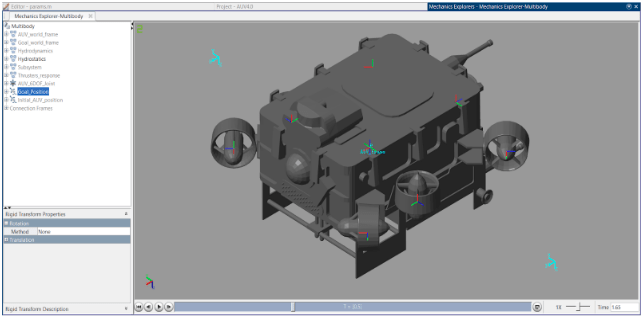
Simulation
We adopted an emphasis on software simulations as part of our test-driven software development cycle, using tools such as Gazebo and MatLab Simulink.
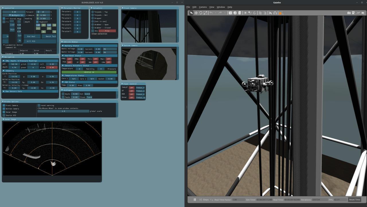
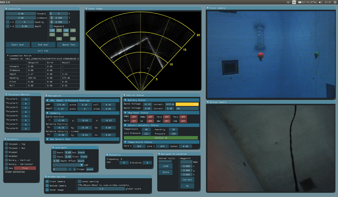
Control Panel Interface
The Bumblebee 4.0 Control Panel displays telemetry information, camera and sonar images, which aids in the monitoring of sensors and actuator data for system analysis during operational deployments when connected over the tether. The control panel is also used for control of the vehicle during teleoperation mode.
The software stack has a logging system which is used to capture telemetry and video information, and log messages during both tethered and autonomous operations. The software is capable of replaying logged data and streaming into the user interfaces allowing for post mortem analysis of the mission and evaluation of the collected data.
Mapping Interface
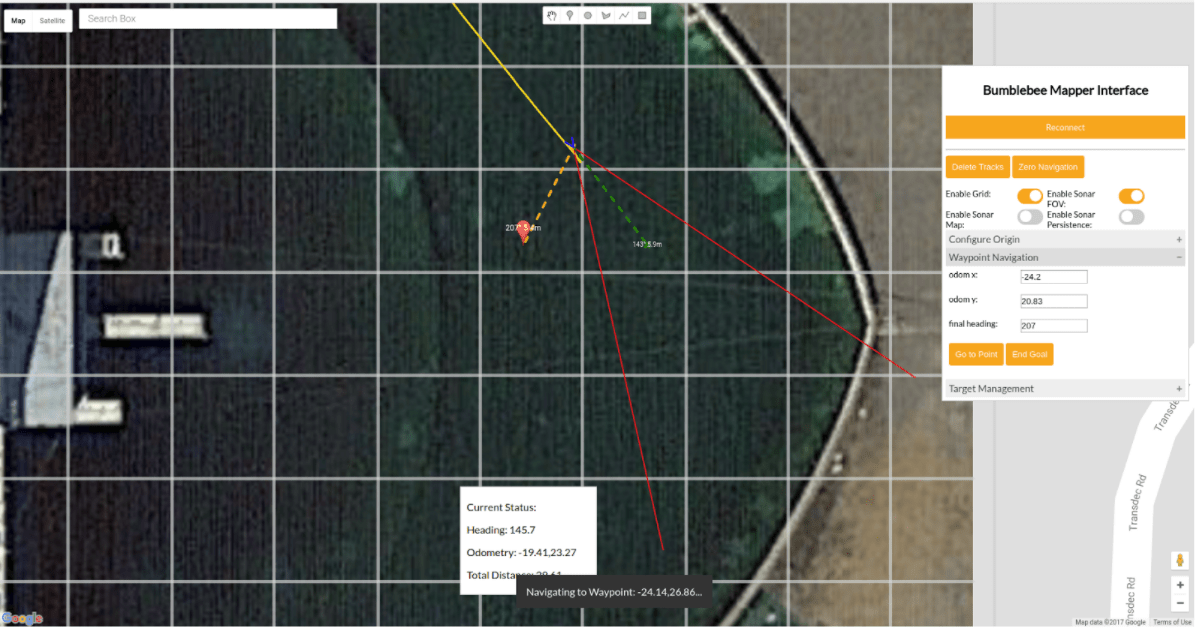
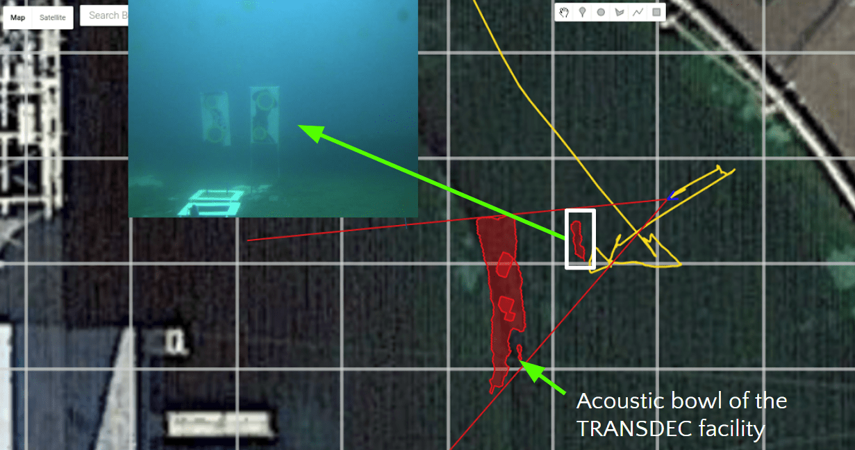
Apart from the control panel interface, the Bumblebee 4.0 vehicle has a mapping interface which enables point-and-click operation of the vehicle, moving it to the location indicated when used in tele-operation mode.
The mapping interface maps out key sonar objects in the area and projects it onto the mapping interface so that the operator can directly correlate its real world position with the actual coordinate of a certain sonar object.
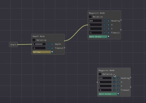
Mission Planner
Vehicle dynamics during an autonomous mission is fully controlled by the mission planner, which directs task nodes, controls trajectory between tasks and manages time.
The highly modular software architecture complements the functionality of the mission planner. The mission planner’s multi-threaded structure allows for simultaneous execution of mission tasks and watch states that serve to keep track of the mission and task statuses. The mission planner also manages contingency states to allow for recovery via the saved waypoints during the missions.
Mission runs can be dynamically built from user input, providing an option to test task nodes independently in addition to a full mission test.
Underwater Perception and Tracking
Sensor Fusion
The AUV is equipped with two machine vision cameras and an imaging sonar for forward and downward perception. Leveraging upon the benefits of both the sonar and camera, the AUV is capable of highly robust perception and tracking of objects underwater.
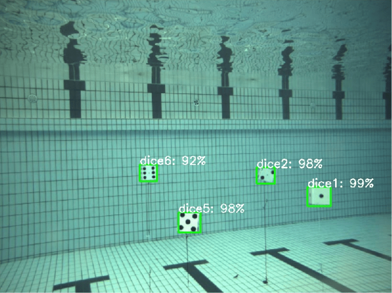
Deep Learning
Deep Learning was also implemented for detection of more complex objects. With this newly introduced feature, our AUV obtained a result of 0.933 for the mean average precision for detection of various underwater obstacles for RoboSub.
Navigation Suite
The navigation sensor suite consists of a 9-axis Sparton IMU, a 6-axis STIM300 IMU, a DVL and a barometric pressure depth sensor. An error state Kalman Filter is used to obtain much higher accuracy than each sensor can provide independently. The AUV navigation system is capable of performing accurate local and global navigation.
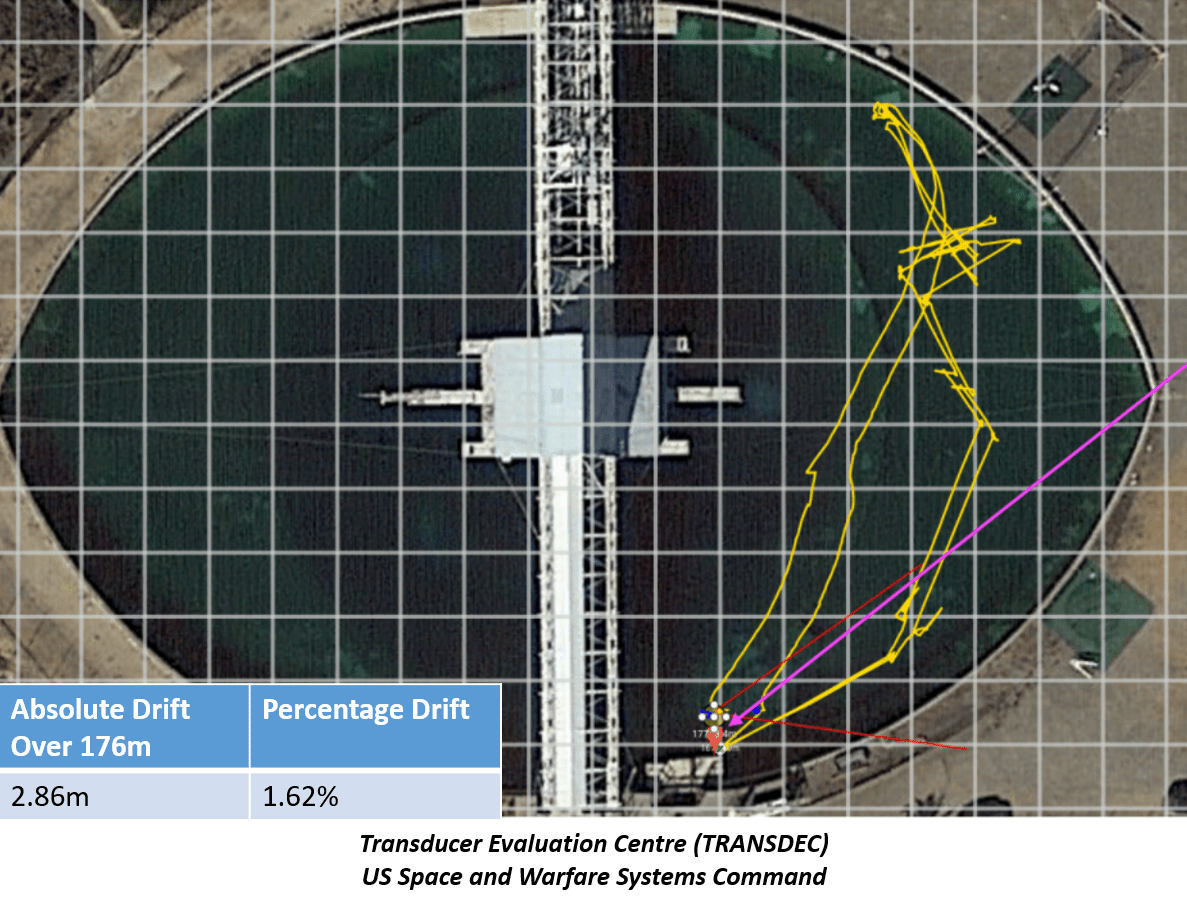
The current navigation system was evaluated over 176m with 1.62% of drift measured based on its DVL/IMU sensor fusion.
Autonomous Manipulation
With a highly accurate navigation suite and robust object perception and tracking, the AUV is capable of fully autonomous manipulation of objects. We have tested various types of manipulators, ranging from grabbing arms, to marker droppers, to mini projectiles. The software on the Bumblebee AUV is capable of different types of manipulation.