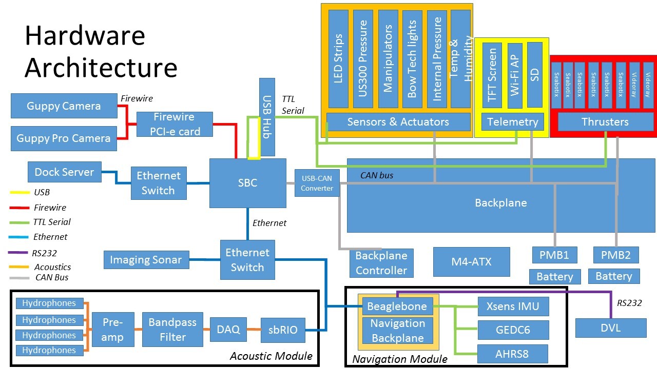
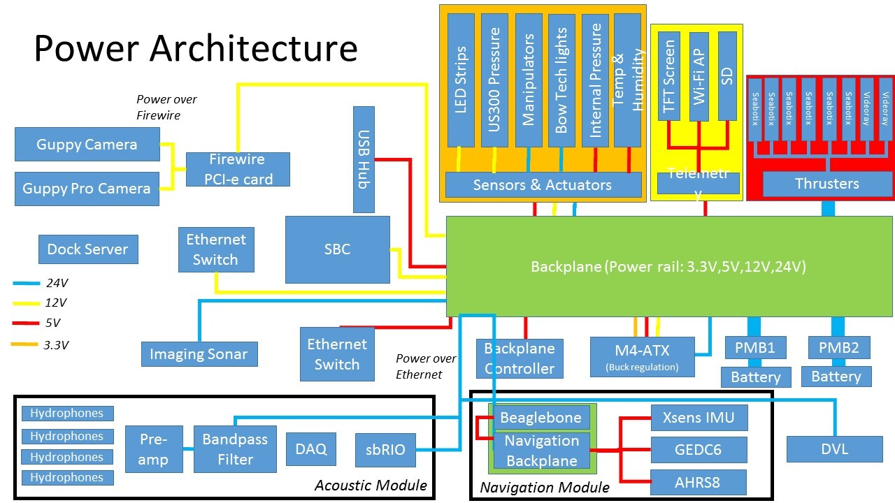
The electrical system comprises of the power, sensors and actuators and the computer subsystems. This year, one key feature that was newly implemented was the backplane, which helps to integrate most of the boards together. New sensors and actuators have been redesigned and additional ones are integrated together with the backplane.
The main computer board has been updated, which hosts a quad core i7 processor for fast multicore software processing. The components are integrated into a single multi-level rack fitted into a single hull.
Navigation System
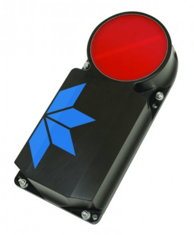
The navigation system on board of Bumblebee 3.0 uses 2 Inertia Measurement Unit (IMU), along with a Doppler Velocity Log (DVL).
The IMUs provide critical inertial data at a rapid rate of 100 Hz. The IMU’s proprietary algorithms ensure the output of correct data despite the presence of electromagnetic interference generated by the BumbleBee’s suite of electronics and thrusters.
The DVL is an active sonar system that helps to track the velocity of the instrument via a four-beam solution directed at 30 degrees nominal from the sensor’s ceramic head. The velocity readings obtained are combined with tilt and altitude measurements, then resolved into the three orthogonal x, y and z axes via a least squares fit solution. These resolved readings are further filtered through a direct three-degree of freedom Kalman filter, which serves to attenuate noise. The calculations outputs a more accurate positional coordinate of the vehicle.
Computer System
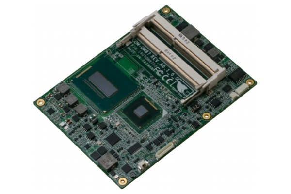
BumbleBee’s software system is powered by an Intel Core i7-3610QE quad core processor on an Aaeon PCM-QM87 motherboard along with a 512 GB SATA SSD (Solid State Drive). This is an upgrade over last year model of Aaeon PCM-QM77 motherboard.
A USB hub is employed to help interface the embedded sensors and actuators as well as other serial devices. The imaging sonar is connected via Ethernet with a PoE (Power over Ethernet) connection to the SBC, dedicating imaging sonar bandwidth to the main computer. VGA and USB ports are exposed to allow external debugging of the software systems.
The computer is connected to dockside through a 100 Mbps Ethernet tether. The vehicle is networked to a Gigabit switch that connects to the sbRIO 9602 and surface router.
Power Management
The vehicle is powered by two 10000 mAh LiPo (lithium polymer) batteries providing testing time of approximately two and a half hours before a recharge is required. Each LiPo battery is installed into a battery pod which allows for both charging and discharging. With 2 batteries, hot swap capability is possible. which helps in the efficiency of our vehicle. Within the pod, the batteries are connected to PMB (Power Monitoring Boards) which monitor vital power statistics such as current draw, cell voltage and capacity. The custom fabricated BMB has been designed to withstand a maximum current of 30 A.
A battery charging box was redesigned slightly, for ease of charging and transporting. This box enables quick deployment of mobile charging stations. This battery charging box supports parallel charging of two battery pods of up to 50 A per channel at one go.
Acoustics
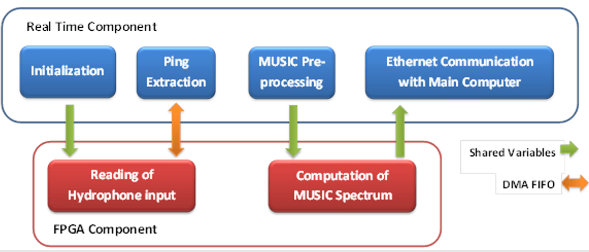
BumbleBee’s acoustic sub-system has four Teledyne hydrophones in a square array, integrated with custom fabricated analog and digital boards. The high-resolution MUSIC (MUltiple SIgnal Classification) algorithm is used for localising the acoustic pinger.
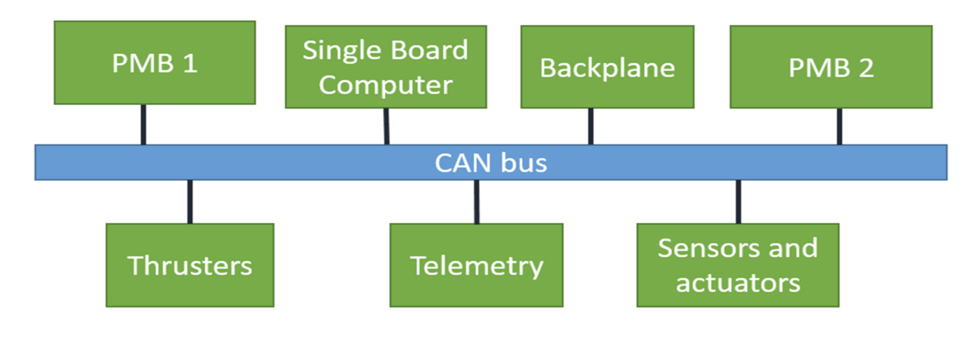
Controller Area Network (CAN)
The CAN protocol is implemented for communication between devices in the AUV. It is deployed on all the daughter boards, the Power Monitoring Boards, the Electrical Backplane and also the SBC. The deployment of CAN in the Bumblebee System eliminates single point of failure from Bumblebee 2 by requiring the SBC to in the communication loop. With CAN, hardware devices are able to exchange data in a peer to peer fashion over a robust differential CAN bus without additional wiring overheads between devices.