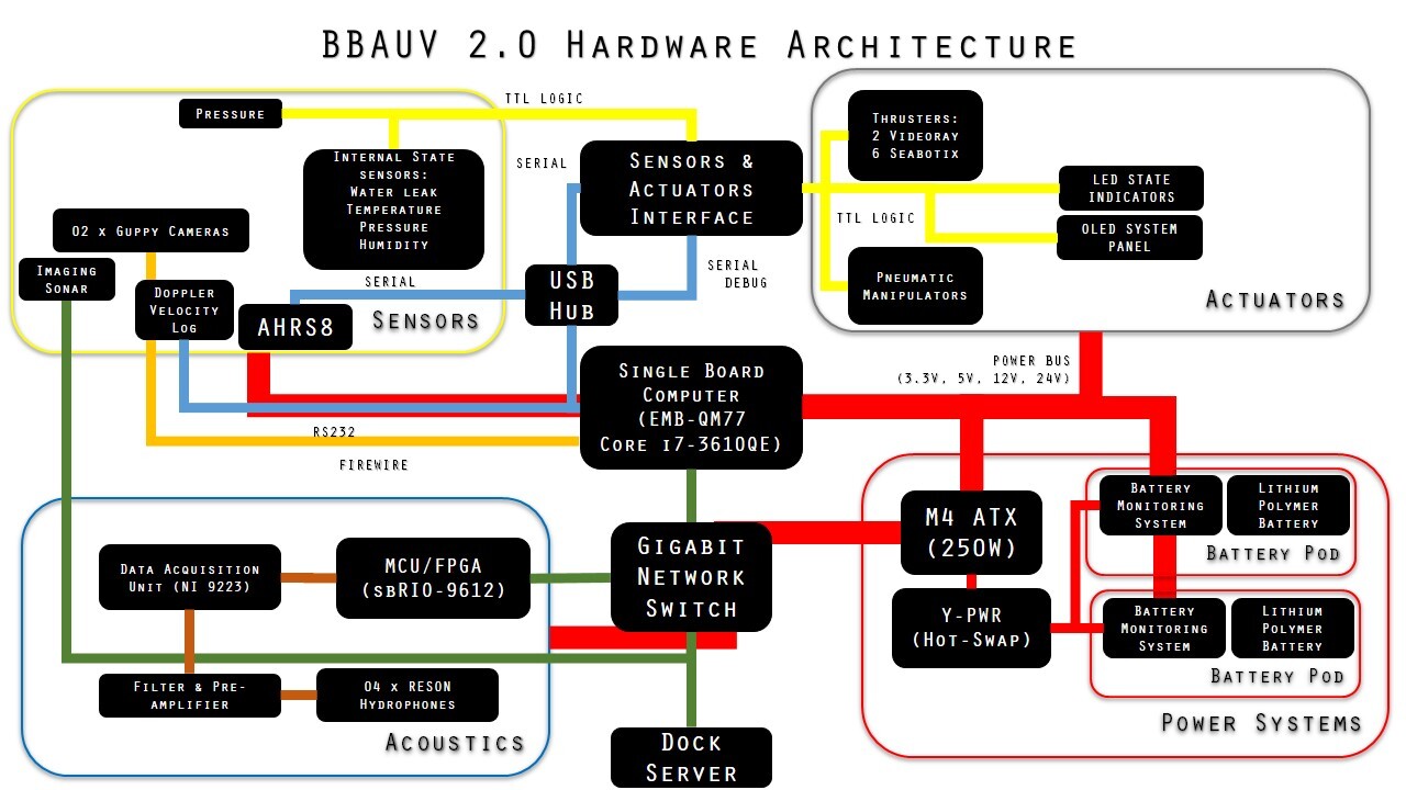
The electrical system comprises of the power, sensors and actuators and the computer subsystems. The previous OpenUPS power subsystem has been replaced with the integration of Battery Management Boards. The sensors and actuators have been redesigned and additional ones are integrated. The main computer board hosts a quad core i7 processor for fast multicore software processing. The components are integrated into a single multi-level rack fitted into a single hull.
Navigation System
Navigational Sensors
Sparton AHRS-8 IMU: The Sparton AHRS-8IMU (Inertia Measurement Unit) provides critical BumbleBee Autonomous Underwater Vehicle 4 inertial data at a rapid rate of 100 Hz. The IMU’s proprietary algorithms ensure the output of correct data despite the presence of electromagnetic interference generated by the BumbleBee’s suite of electronics and thrusters.
Teledyne RDI Explorer DVL: The DVL (Doppler Velocity Log) is an active sonar system that tracks the velocity of the instrument via a four-beam solution directed at 30 degrees nominal from the sensor’s ceramic head. The velocity readings obtained are combined with tilt and altitude measurements, then resolved into the three orthogonal x, y and z axes via a least squares fit solution. These resolved readings are further filtered through a direct three-degree of freedom Kalman filter, which serves to attenuate noise. The calculations outputs a more accurate positional coordinate of the vehicle.
Navigation
The data provided by the navigational sensors are fused together via simple trigonometric equations to generate a global position vector. The odometric data obtained from this vector allows the vehicle to navigate precisely to any given spatial co-ordinate.
Computer Systems
BumbleBee’s software system is powered by an Intel Core i7-3610QE quad core processor on an Aaeon PCM-QM77 motherboard along with a 512 GB SATA SSD (Solid State Drive). This upgrade from the previous 16 GB SSD accommodates more software data and rosbag data collected during practice runs.
A USB hub interfaces the embedded sensors and actuators as well as other serial devices, i.e. two BMBs and the AHRS-8. The imaging sonar is connected via Ethernet with a PoE (Power over Ethernet) connection to the SBC, dedicating imaging sonar bandwidth to the main computer. VGA and USB ports are exposed to allow external debugging of the software systems.
The computer is connected to dockside through a 100 Mbps Ethernet tether. The vehicle is networked to a Gigabit switch that connects to the sbRIO 9602 and surface router.
Power Management
Power Monitoring and Management
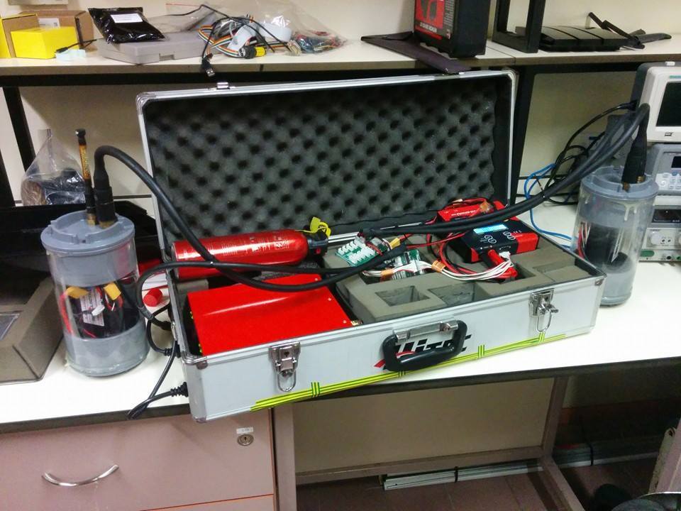
The vehicle is powered by two 7800 mAh LiPo (lithium polymer) batteries providing testing time of approximately two and a half hours before a recharge is required. Each LiPo battery is installed into a battery pod which allows for both charging and discharging. Within the pod, the batteries are connected to BMB (Battery Monitoring Boards) which monitor vital power statistics such as current, cell voltage and capacity. The custom fabricated BMB has been designed to withstand a maximum current of 30 A. This monitoring system allows for tracking of power statistics of each of the battery pods and has proved to be more reliable than the previous off-the-shelf OpenUPS system.
A battery charging box was designed for quick deployment of mobile charging stations. This battery charging box supports parallel charging of two battery pods of up to 50 A per channel at one go.
Power distribution is simplified by PMB (Power Management Boards) that replaces the OpenUPS of the previous vehicle. This change improves the power efficiency without the OpenUPS step down regulator and has lesser points of failure. Diagnostics are streamed from the PMB via serial connection to the SBC (Single Board Computer). The power system utilizes a M4 ATX to regulate power in order to generate three voltage rails to power up the SBC and the sensors and actuators. A Y-PWR provides hot-swap capabilities for the batteries without shutting down the motherboard.
Passive Sonar
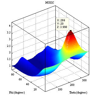
BumbleBee’s acoustic sub-system has four Teledyne hydrophones in a square array, integrated with custom fabricated analog and digital boards. The high-resolution MUSIC (MUltiple SIgnal Classification) algorithm is used for localising the acoustic pinger.
Hydrophone Array
With the MUSIC beamforming algorithm, the inter-element spacing d between each hydrophone element should not exceed half of the carrier wavelength to avoid spatial aliasing. The compact 9.5 mm Teledyne TC 4013 hydrophone can achieve this condition in a square array with d of 1.5 cm. This hydrophone mount is designed on SolidWorks and fabricated precisely using laser-cutting technology.
Analog and Digital Boards
An analog pre-amplifier and bandpass filter board is fabricated for signal amplification and noise attenuation. The analog signal is digitally sampled at a rate of 250 kS/s by a NI (National Instruments) NI9223 Analog Input Module (DAQ). Array signal processing algorithms are programmed with Lab-VIEW 2012 on NI sbRIO NI9206 (FPGA). The FPGA transmits the computed FFT (Fast Fourier Transform) information to the SBC via the UDP protocol, where the MUSIC algorithm is performed.
Algorithm
The sampled signal is passed into an elliptic 10th order band pass filter with a center frequency set to the pinger’s frequency. This digital filter has a narrow 3 dB bandwidth of 5 kHz. The start of each ping must be correctly identified before information on its phase can be computed. This is estimated using the peak and dynamic threshold detection. Dynamic thresholding is preferred over simple thresholding because the received power varies with distance. Only the initial segment of the ping (Line of Sight signal) is extracted for post processing. This avoids phase distortion when multipath reverberation effects set in at a later stage. The amount of samples extracted is defined by a FFT size of 128 points determined by extensive experimentation.
FFT-operations are performed on the extracted ping to verify that the identified signal falls within the frequency range of the pinger. If the signal falls within the defined frequency range, the complex numbers (FFT points) associated with the peaks of the power spectrum are extracted. These FFT points are used to compute the covariance matrix required in the MUSIC algorithm.
In this application, the spatial covariance matrix is computed over a period of 3 pings. The eigenvectors corresponding to the signal and noise subspaces are obtained from eigen-decomposition of the spatial covariance matrix. The MUSIC algorithm searches for a set of azimuth θ and elevation -ø where the array steering vector ∝ (-ø; θ) is the most orthogonal to the noise eigenvectors Vn. The direction of the pinger is indicated by the maximum point of Pmusic derived from the 2-D search in θ and -ø.
Control Systems
BumbleBee 2.0 has six degrees of freedom: surge, sway, heave, roll, pitch and yaw. Six PID (Proportional Integral Derivative) control loops are tuned to control the vehicle’s underwater dynamics. The PID controllers are designed with the following
Considerations:
- Low pass filter for the derivative component to reduce the exponential effects on sensor noise
- Variable period time sampling for more accurate computation of the integral and differential components
- Weighted set points to reduce transient effects in set point changes
- Integrator windup protection for when actuators are unable to fulfil the PID Controller requirements
The PID control loops have been improved for dynamic allocation of actuator limits, allowing greater output in specific degree of freedoms. Velocity controllers for the surge and sway domains have been implemented for more precise manoeuvring of the vehicle during mission tasks. A User Interface was designed by the software team to facilitate PID Tuning.
Sensor and Actuator System
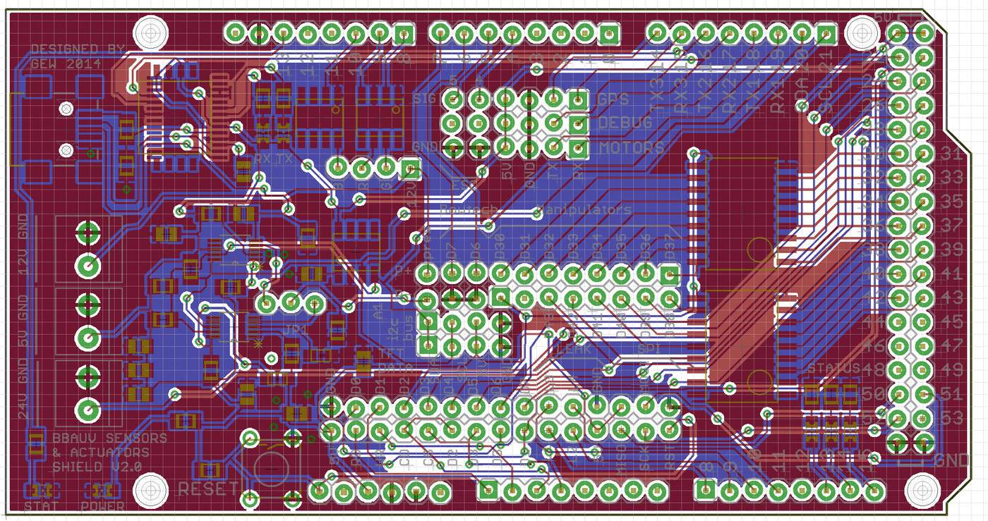
BumbleBee 2.0 presents a redesigned and custom fabricated PCB (Printed Circuit Board) for the sensors and actuators shield. The Arduino Mega 2560 microcontroller developmental board is based on the previously used ATMega 2560 microcontroller. The previous shield design was continued for the quick swap of microcontroller crucial for modular debugging during port or component damages.
New sensors such as internal pressure and humidity sensors are added to the current suite of the AHRS-8 IMU, depth and temperature sensors. This board also interfaces the six Seabotix thrusters and the pneumatic manipulators. The current thrusters are enhanced by including actuator controls to the electronic speed controllers operating on the two Videoray surge thrusters.
In addition, LED strips are integrated as state indicators, while a TFT LCD screen display provide visual feedback on the system sensor status. These indicators are especially useful during autonomous runs for understanding the vehicle’s current state.