Architecture

The Software Architecture of Bumblebee is based on the Robot Operating System (ROS) Software Framework from Willow Garage which encompasses the underlying messaging infrastructure for inter-process communications in our distributed system.
The basic unit in ROS is a single node which is a process within itself. ROS offers two key forms of distributed messaging, the concept of Topics which is essentially data streaming over TCP or UDP, and the concept of Services which is an XML-RPC request-response call. Topics were used where real time data updates were required for real time processing and Services were used for one time state updates or to trigger transitions in the system.
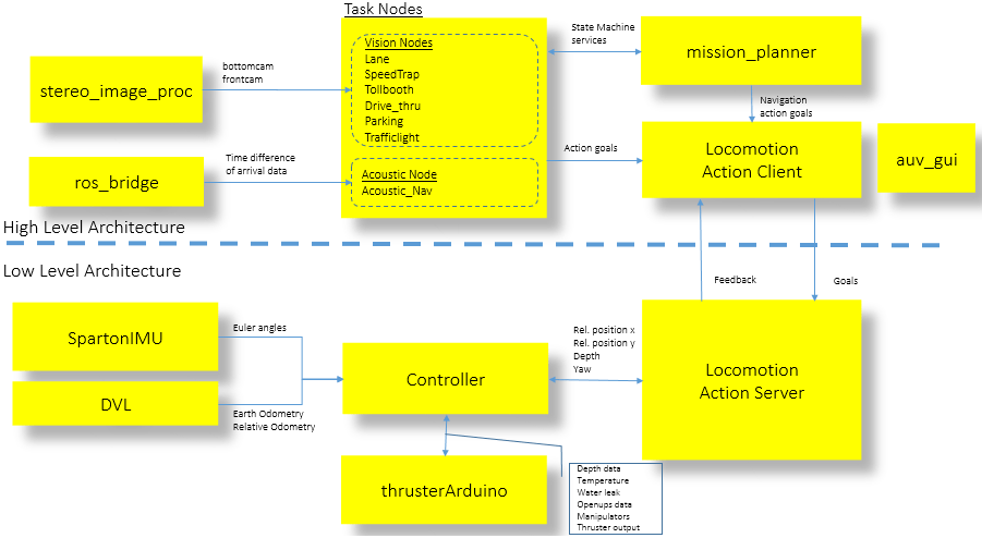
BBAUV’s Software Architecture comprises of two parts:
- A High level Architecture where most of the vision processing and high level Artificial Intelligence exists in performing object recognition, motion control and task completion.
- A Low level Architecture where the core sensor and actuator drivers are connected to a low level Controller which is responsible for vehicle locomotion and environmental sensing.
Locomotion and navigation within the AUV were achieved with the use of an Action Server and Action Clients based on the actionlib API from ROS. The establishment of an action server allowed for nodes to perform actuation across processes. In addition this made distributed control of the vehicle over the network possible since connection to an Action Server was established over TCP/IP.
The Action Client and Action Server act as the bridge between the High level and Low level Architecture in our Software systems.
Parameters
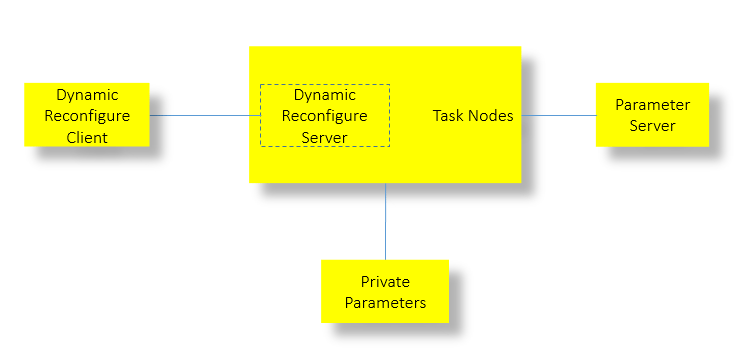
A shared memory model between nodes called the Parameter Server was also utilized for the storage and retrieval of global shared parameters. Local parameters within each node were either statically configured upon initialisation as Private Parameters or were dynamically configured with the dynamic reconfigure API and was generally heavily utilised for the various mission requirement. Each node would spawn a dynamic reconfigure server which handled calls from the dynamic reconfigure gui client (also part of the ROS framework) as and when changes were triggered by the user to each parameter. The ability to dynamically reconfigure parameters on the fly proved to be crucial for us.
Finite State Machine Design
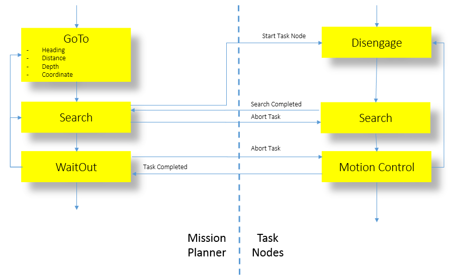
The Smach State Machines API was used in the high level software design for the mission planner and task node interactions. Each node has a few generalised states as illustrated in the diagram above. Inter-nodal communication is achieved with ROS Services. Inter-nodal communication consists of the following four generalised state triggers: Task start, Task search completed, Task completed and Task abort. This structured communication mechanism coupled with our Finite State Machines design provided strong software foundations for a real time system.
Finally within each node multi-threaded ROS callbacks were used extensively for non-blocking reads or concurrency. ROS’s multi-process and multi-threaded framework coupled with the multi-core processor of our quad-core Single Board Computer enabled us to push the software capabilities of Bumblebee further.
The core of the software was written in C++ for the low level drivers and controllers and Python for most of the Computer Vision tasks and High level Artificial Intelligence.
Operating System

The main operating system of choice for Bumblebee was Ubuntu 12.04, Precise Pangolin a variant of the Linux Kernel. Ubuntu was selected for full compatibility with ROS.
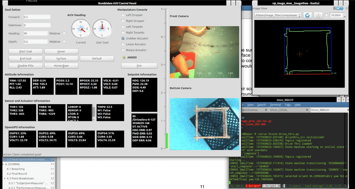
Telemetry
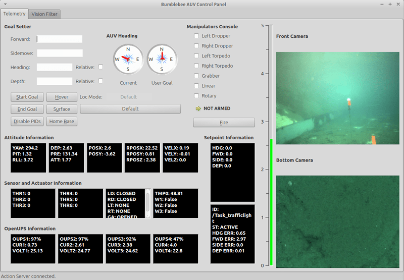
To provide real time updates on the sensor and actuator system on Bumblebee a User Interface was designed to provide the user of the system with detailed information on Attitude, Sensors and Actuators, Power and lastly with locomotion information on its current target locomotion goals. In addition to providing such critical information to the user, the vehicle’s navigation could be charted with the use of the Goal Setter Panel in addition to a few pre-designed vehicle motion states such as Surface, Hover and the disabling of PIDs to disengage the Control Systems. On top of that, a manipulator’s console is provided for manual control of the various pneumatic actuators on the vehicle.
Vision Filter Suite
The Vision Filter Suite was designed for the Computer Vision Team to apply quick filter chain to imagery collected on the fly from the camera systems on board. This proved critical in the quick adjustment of Vision parameters on the fly during practice runs to achieve the optimal settings for the vision algorithms to work perfectly.
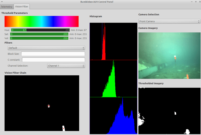
The Vision filter suite now offers the capability to perform image segmentation with thresholding in the HSV colour space (which is used primarily in our vision algorithms) with real time feeds on the results of the filter applied. A histogram of the current imagery allows users to more optimally select their threshold ranges on the fly. The current filter chain from the current running vision nodes is also provided for easy debugging of vision algorithms with live camera feed and processed image feeds all placed within the same interface.
Lastly, as an experimental feature, other forms of thresholding can be explored such as adaptive thresholding methods of local analysis and Otsu’s algorithm.
Mission Planner
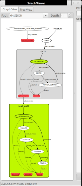
The AUV’s mission planner is written using ROS’s SMACH state machine library. With the library, the mission is able to execute states linearly, concurrently or iteratively by using the corresponding state containers. The library also allows for nested state machines which help the team to reuse mission code between tasks; this greatly simplifies the code and reduces error. The other important aspect about SMACH is the ability to visualize using the smach_viewer software. By spawning an introspection server within the mission code, the mission developer is able to visually see the state machine and debug any mistakes prior to running a mission.
There are a few main states used in BBAUV’s mission planner. Common to all states is a time out feature that will pre-empt the state when time is up. This allows the mission to move on in the event that the vehicle cannot see the task element.
GoToHeading– brings the vehicle to a particular heading; accepts both relative and absolute headingGoToDistance– Bring the vehicle to a particular distance in either the surge or sway directionGoToDepth– Brings the vehicle to a particular depth; also checks to make sure that the vehicle does not surface unintentionallyNavMoveBase– Connects to ROS’s move_base action server to bring the vehicle to a global coordinate in a map frame via a global pathStoreGlobalCoord– Stores global coordinates from DVL into roscore’s Parameter Server. This is useful if the mission requires the vehicle to return to a “last seen” locationWaitOut– This state waits for the vision task state machines to completeLinearSearch– Move along the sway or surge axis and turn on search mode of vision task
Vision Processing
ROS provides driver nodes for both the Bumblebee2 and Firefly cameras. Since both camera systems return their images in a Bayer encoded format, image processing nodes need to be run to convert the images into RGB format. Additionally, a stereo image processing node is run so that the stereo images provided by the Bumblebee2 stereo vision camera system can be used to compute depth images from which distance to obstacles is obtained. The image processing nodes also perform rectification of the images when provided with camera calibration data.
Each task of the competition is handled by a node dedicated to that task, with each node being divided into a vision processing component and a motion control component. Using the ROS publisher-subscriber model, the task nodes obtain their images by subscribing to the image topics published by the image processing nodes. Common computer vision techniques used by the task nodes include color thresholding in HSV space, contour detection and Hough transforms for finding lines and circles.
To optimise network bandwidth to view the camera streams effectively either in image_view from ROS or in the Telemetry software we developed for the AUV, JPEG lossy compression is used for the image stream transfers. Similarly for rosbags, which is the recording of mission data for future processing, the camera image streams are compressed with JPEG lossy compression to minimise the space requirement of the bag data.
Acoustics Interface
A LabView GUI is used to observe and change parameters for the acoustic systems.
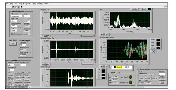
Having known which frequency that we are interested in, we firstly do a band pass filter to remove all components that we are not interested in. For a clean environment, a Butterworth filter is our best choice since it will maintain the same amplitude as the normal signal. However, an Elliptic filter with ability to cut frequency off sharply is also implemented for a noisier environment.
Then, we extract the portion of the sound with the strongest signal and check if the frequency there is in the desired range using FFT library from Labview. If the frequency is correct, we go to the next step where we only extract the very initial portion of the signal where the signal is still clean and the constructive and destructive interference from its reflection is not severe.
To obtain the Time of Arrival, we used the Peak Detection Algorithm to find the position of the first peak of this signal. A threshold is required.
After much experimentation, we realized that the amplitude of filtered noise from the environment and the strength of the sound will fluctuate while the AUV moving, so a static amplitude threshold will not work. Moreover we also find out that the amplitude of noise never exceed a specific range. Hence, a dynamic amplitude threshold algorithm is developed to solve this problem. The dynamic threshold is calculated by finding highest peak of the noise and scale it up. The scaling factor must be chosen to ensure all the other noise is less than the threshold and the first real peak is higher than that threshold.