| Sensors | Depth: Measurement Specialties US300 30PSI Gauge Velocity: Teledyne Workhorse 1200kHz Doppler Velocity Log | Sensors | IMU: 9-axis DOF Sparton AHRS-8 Acoustics: Sparton PHOD-1 Hydrophones |
| Embedded System | ATMega 2560, Arduino Mega Development Board | Digital Signal Processing | NI Single Board RIO 9612 Analog Input Module NI9223 |
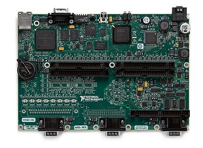
| Single Board Computer | EMB-QM77 Motherboard Intel Ivy Bridge Core i7-3610QE 16GB SSD 8Gb RAM | ATX Power Supply | M4-ATX 24V, 12V, 5V, 3.3V |
| Vision | Forward: Bumblebee Stereo Camera Downward: FireFly MV Camera | Battery Capacity and Management | 21,600 mAh 4 x OpenUPS Y-PWR for Hot Swap |
| Propulsion | 6 Seabotix BTD150 Thrusters to give 5DOF | Motor Controllers | 6 x Pololu Simple Motor Controllers |
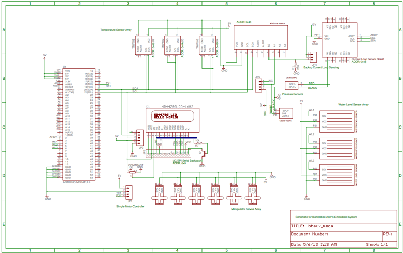
Embedded System
Real time processing on Bumblebee was achieved with the use of the Arduino Mega development board based on the ATMega 2560 microcontroller from AVR. The Embedded System was primarily used for sensing and actuation. A timer interrupt driven kernel was designed to handle the many sensitive timing requirements of the various sensors and actuators on board the AUV.
Internal Sensors
To monitor the internal status of the hull, the system was outfitted with an array of temperature sensors to detect overheating conditions of the electronics rack and also an array of water leak sensors lined at the bottom of the hull to detect for water leaks.
Pressure Sensor
The US300 Gauge Pressure Sensor from Measurement Specialities was used for depth measurement of the vehicle. Current loop sensing was used for signal acquisition and was coupled with a discrete low pass filter to clean up noise in the signal for stable readings from the sensor.
Actuators
The six thrusters on the system are controlled by Pololu Motor Controllers which generate the PWM signal required for brushed DC motor control. These motor controllers were daisy chained together on a single serial bus to accept speed commands from the Arduino. This reduced the number of I/O required and simplified the wiring implementation. To reduce the amount of time taken for a single update of the motor speeds over all six motor controller, increased due to serialisation, the serial baud transfer rates were set to the maximum setting of 115200 bps.
The pneumatic manipulators are actuated from a total of seven Single Pole Single Throw (SPST) relays. Each individual relay controls one of the seven pneumatic actuators responsible for the actuation.
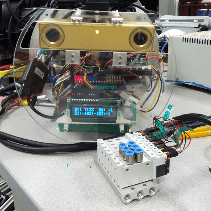
LCD Display
The vehicle has a 16 x 2 OLED LCD Display to provide feedback of the vehicle status for the diver or on the fly monitoring of the system. The LCD screen displays the current power levels of the four batteries, the temperature of the internal hull and also the presence of any water leaks.
Passive Sonar System
To complete the acoustic task, the AUV uses an array of 4 Sparton PHOD-1 hydrophones positioned up front to pick up the pinger signals. The signals picked up by the hydrophones would then be pre-amplified before noise filtering with an analog high pass filter board which was developed by the Acoustics Research Laboratory, NUS. Thereafter the cleaned up signal would be sampled by the sbRIO9612 with the support of an Analog Input Module, NI9223, at a rate of more than 300kS/s simultaneously. From the input signal, the onboard microcontroller of the sbRIO9612 would employ a thresholding algorithm to acquire the portion of the ping and then translate it into time difference of arrival of each hydrophone.
The time difference of arrival will then be sent to the Core i7 Single Board Computer for triangulating computation which outputs the direction and position of the pizza box relative to the vehicle. To reduce the need for sway movement, the AUV will first turn towards the direction of the pinger signal, and then use its navigation system to move towards to the position of the pizza box.
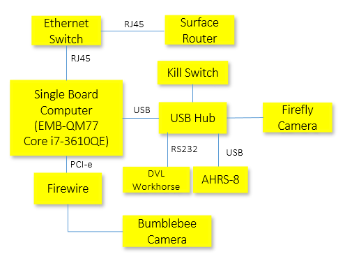
Computer System
Power Systems
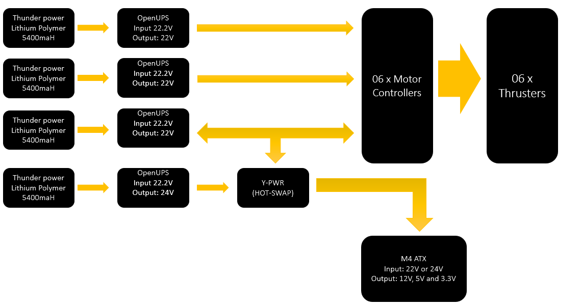
BBAUV’s power system consists of 4 x 5400mAH 6-Cell lithium polymer batteries, 4 x battery management boards, 1 x Hot Swap Load Sharing Controller Board and 1 x 250W DC-DC ATX power supply.
Each battery management board connects to a battery and provides coulomb counting, programmable voltage output and time out auto shutdown feature when the battery runs low on power. Each battery board also allow for the input of the AC-DC power for powering up by the bench. The 250W DC-DC ATX power supply provides high amperage 12V, 5V and 3.3V rails to a variety of sensors, computers and boards in the vehicle. The battery management boards provide power to the 6 thrusters. Power path of the thrusters and computer/sensors are totally independent to reduce any chance of noise interferences.
Control System
The vehicle offers four axis degrees of freedom in the x,y and z planes and also yaw rotation. Pitch is stabilized to the horizontal and roll is righting moment stabilized. Five Proportional Integral Derivative (PID) feedback controllers were used for the control system in the degrees of freedom.
To obtain stable vehicle dynamics, the PID controllers were designed with the following considerations:
- Derivative component low pass filtered to reduce the exponential effects of sensor noise
- Set point weighting to reduce transient effects in set point changes
- Integrator windup protection when actuators are unable to fulfill the requirement of the PID Controller
- Time sampling with variable period for more accurate integral and differential component computation during discretisation due to task periods not being guaranteed in a non real-time system.
Each feedback controller was also band limited to a certain range in limit the controller output to be within the limitations of the physical actuator model. Bumblebee’s control loop operates at a 20Hz cycle which proved to be sufficient for us to maintain optimal vehicle dynamics.
Cameras
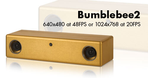
The Bumblebee2 stereo vision camera system by Point Grey Research, Inc provides the forward-facing cameras. These are color cameras with global shutter and fixed focal length, wide-angle lenses. The system communicates via an IEEE-1394b (FireWire S800) connector. It is capable of providing stereo images which are used for computing depth images. The downward-facing camera is a USB 2.0 Firefly MV color camera with a CMOS image sensor and global shutter by Point Grey Research, Inc. It uses a fixed focal length Fujinon lens.