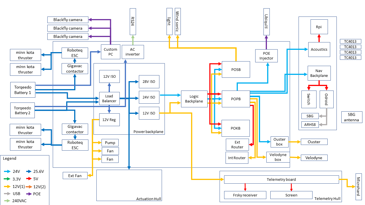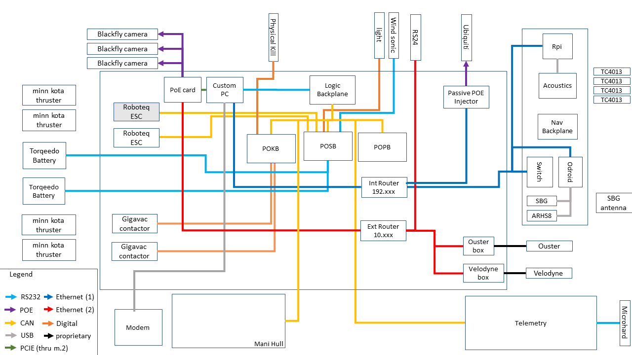
The electrical system of BBASV 3.0 is split into multiple hulls. The main hull contains the electronics which form the backbone of the electrical system, and are categorised into 2 subsystems: power distribution, and sensors and thruster controls.
Ethernet and Controller Area Network (CAN) are our primary methods of communication between the high-level and low-level components, as they ease the adding of new peripherals.
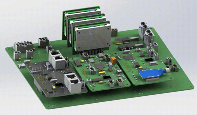
Standardised Backplane
The key design consideration for a standardised backplane was flexibility and eliminating mis-plugging of PCBs onto the backplane. Each of the isolated DC-DC converters could be plugged onto the backplane and the same custom PCB was utilised for all three converters, which output different voltages, by allowing multiple configurations during component assembly. The three daughter boards also utilise the same concept of using a standardised pin mapping to connect to the backplane.
A Quad-FTDI circuit was integrated onto the ASV backplane, providing the interface to reprogram the firmware of multiple daughter boards with a single USB cable on-the fly.
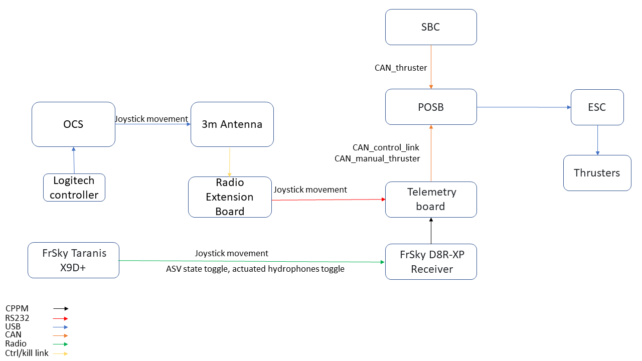
Control Architecture
The Operator Control System (OCS) communicates to the BBASV 3.0 through 2 separate wireless interfaces. The data link is a high-speed link used mainly for the streaming of sensor data such as the ASV camera feed. The control link is a robust long-range link used to send hardware statuses and provide safety features such as an emergency stop for the ASV. The control link uses N2420 radio modems, which form a dynamic mesh network to relay messages from one modem to another. A 10 dBi directional antenna on the OCS maximises the range of the control link to ensure control is maintained of the ASV at all times.
The OCS is also part of the kill system. Activating a latching push button will send the kill command to the ASV via the N2420 radio modem attached to the OCS ground station. To ensure the safe operation of BBASV 3.0, multiple fail-safes are also incorporated into the kill system. If no messages are received from the OCS radio modem, or the sensor board crashes, the thrusters will be killed as a precaution, as the sensor board sends values to the thruster ESCs.
Power Distribution & Power Control
The BBASV 3.0 has a multitude of electronic components that require 5 V, 12 V, and 24 V inputs, powered by 2 Torqeedo Power 26-104 batteries. To enable battery hot-swapping capabilities, the electronics in the main hull receive power from the load-balanced output of the 2 batteries. Moreover, to minimise electrical noise and enhance circuit protection, all our regulators are isolated and have built-in safety features such as over-voltage/current protection. From our extensive testing, we found that the power regulators dissipate large amounts of heat, which pose a problem to the internal temperature of the main hull. As such, the heat sink of the regulators are water cooled.
To enable power control of the various components on BBASV 3.0, the same load switches introduced in BBASV 2.0 were used. This prevents both negative voltage spikes when the input voltage is stepped, as well as inrush current when the control signal is toggled. However, the fuse used was found to be inaccessible and hard to replace. Fuse holders were used instead of soldered-in fuses so that they could be replaced easily while still retaining overcurrent protection.