System Overview
Mechanical Sub-System
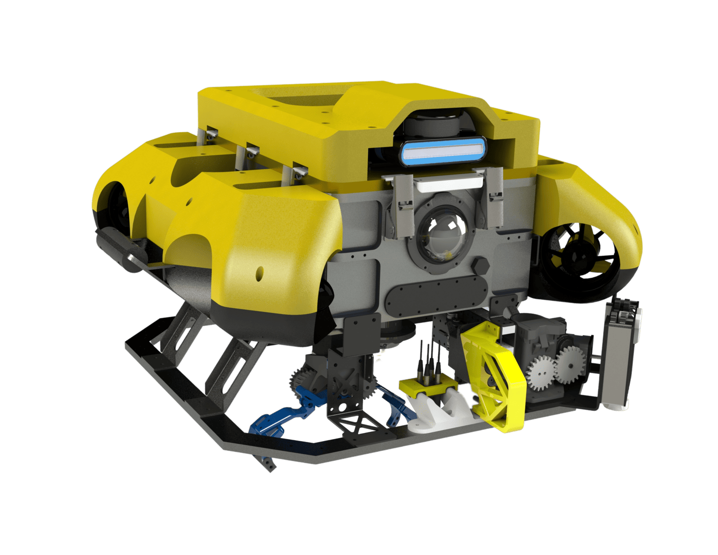
The AUV 4.1 retains the AUV 4.0’s rectangular hull, fibreglass float and octagonal mounting frame to get efficient packing for internal components whilst being resilient to external impacts.
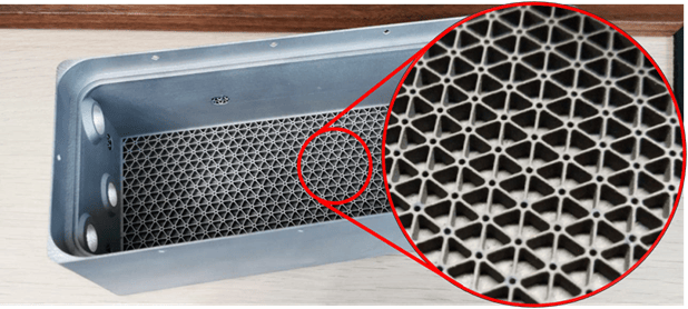
The battery hull was manufactured with 3D metal-printing technology; we also increased the rigidity-to-weight ratio by embedding lattices in the walls and base. Unlike traditional methods, 3D printing allows for tight corners, giving our battery a snug fit. Together, these factors significantly reduce the vehicle’s weight and volume.
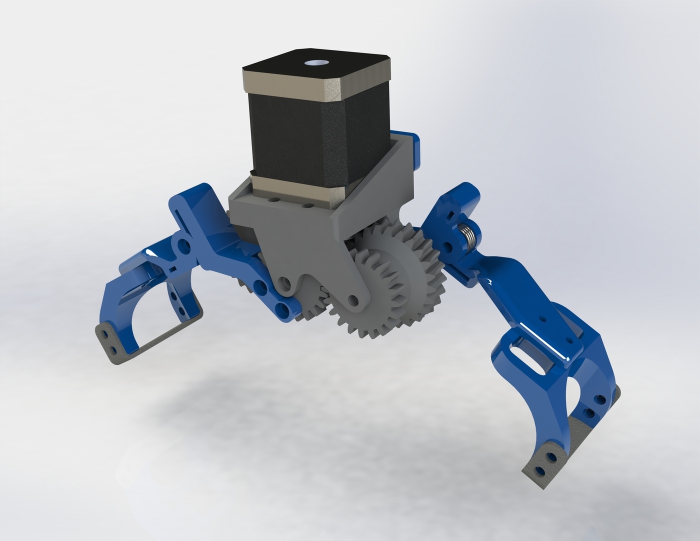
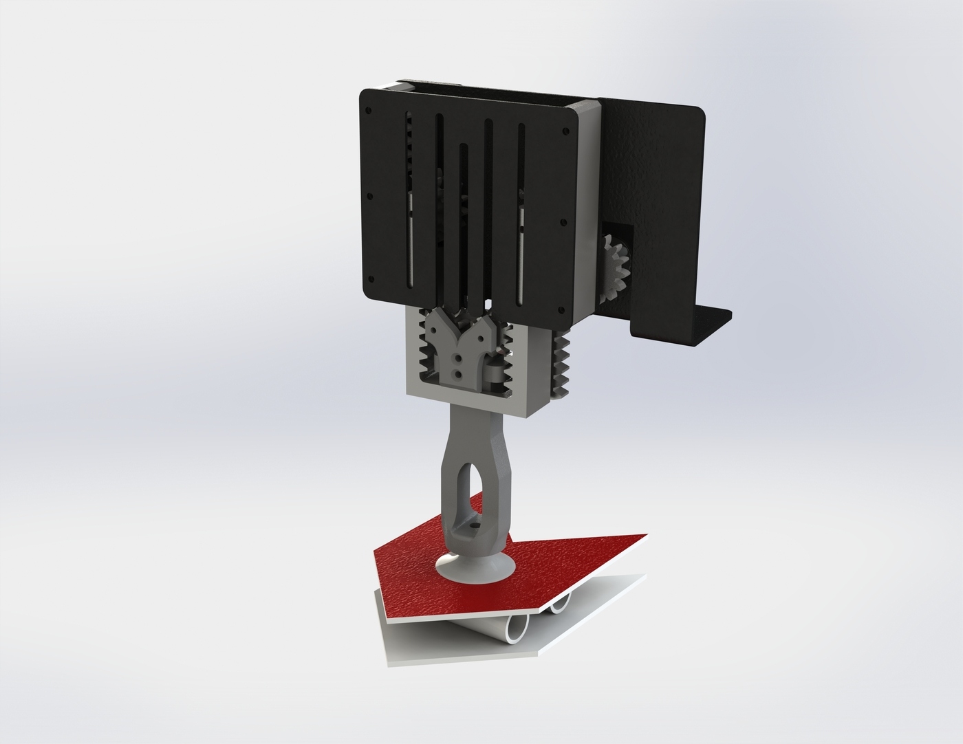
The team has developed two grippers in parallel to increase the range of items it can manipulate. Our stepper motor driven gripper uses torsion springs to make compliant claws that are capped with a layer of rubber for extra grip, making it ideal for grabbing prismatic profiles. To handle large flat objects that can prove challenging for the claw, we developed our own hydraulic vacuum gripper. This arm is extended using a telescopic pulley mechanism further allowing it to reach into narrow areas.
Electrical Sub-System
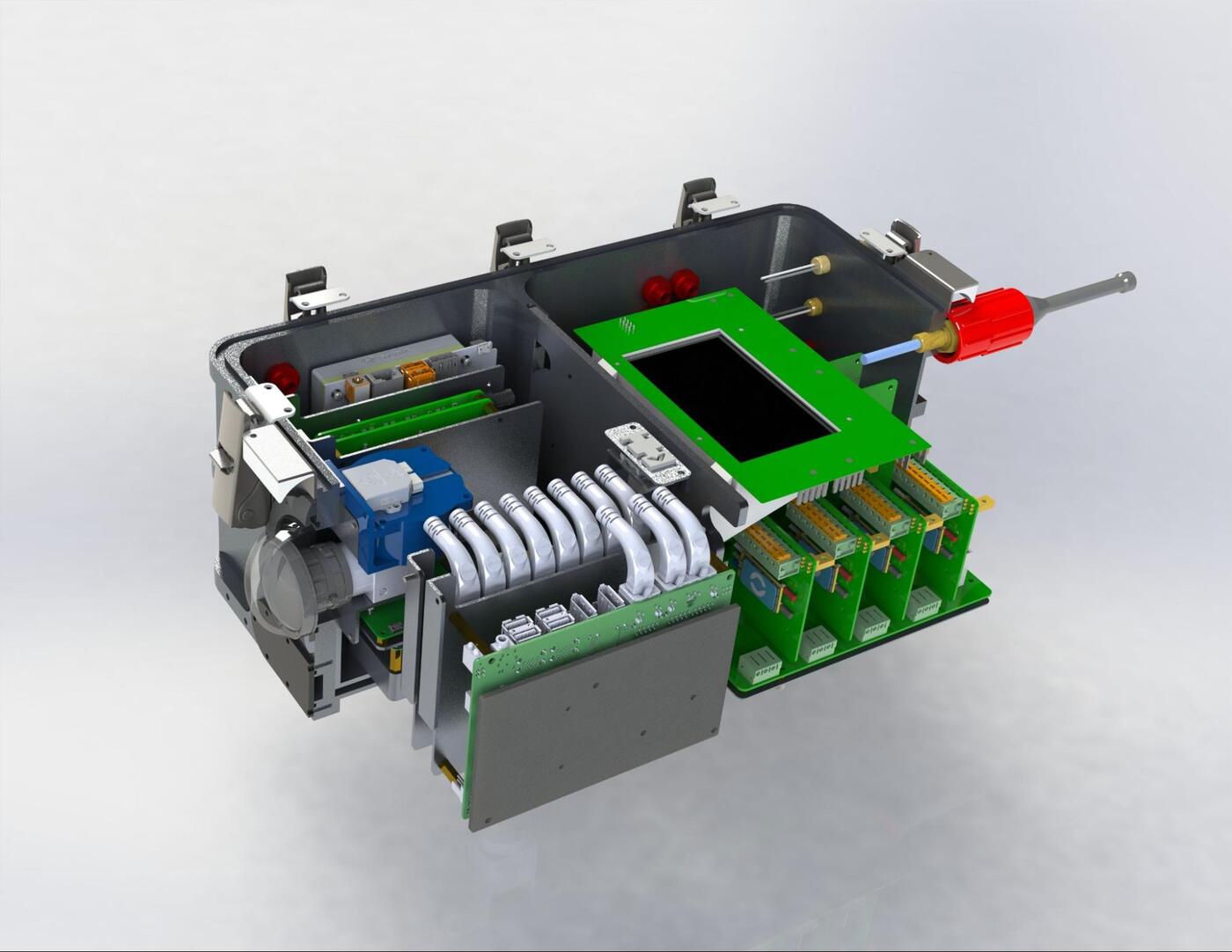
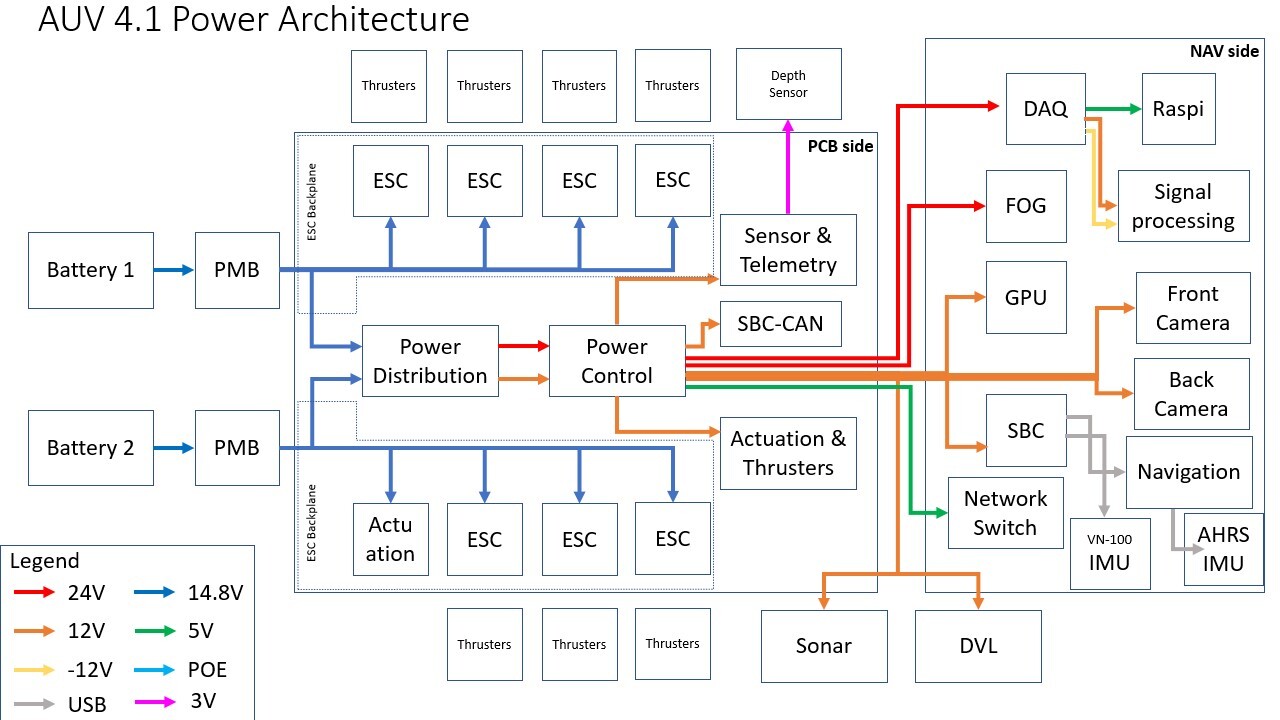
The electrical architecture of AUV 4.1 is centered around implementing quality of life changes into the system, electrical workflow improvements.
Improvements to our network include upgrades on our Operator Control System (OCS) which now supports 4G modem as well as enhanced Wi-Fi connectivity. An in-built screen allows the user to monitor critical vehicle statistics. Furthermore, we have modified our SBC-CAN board which is now able to broadcast telemetry data over UDP.
More power and communication lines were added to the backplanes to reduce the amount of wired connections in the hull. This reduces crosstalk and electrical noise, and aids maintenance and debugging efforts. The new backplanes also have a thicker copper layer that improves heat dissipation and increases the current limit that can be drawn by daughter boards.
A 9-LED configuration was implemeted for greater visibility. To ensure the LEDs are sufficiently cooled and to facilitate heat dissipitation, a copper-cored PCB is used.
Software Sub-System
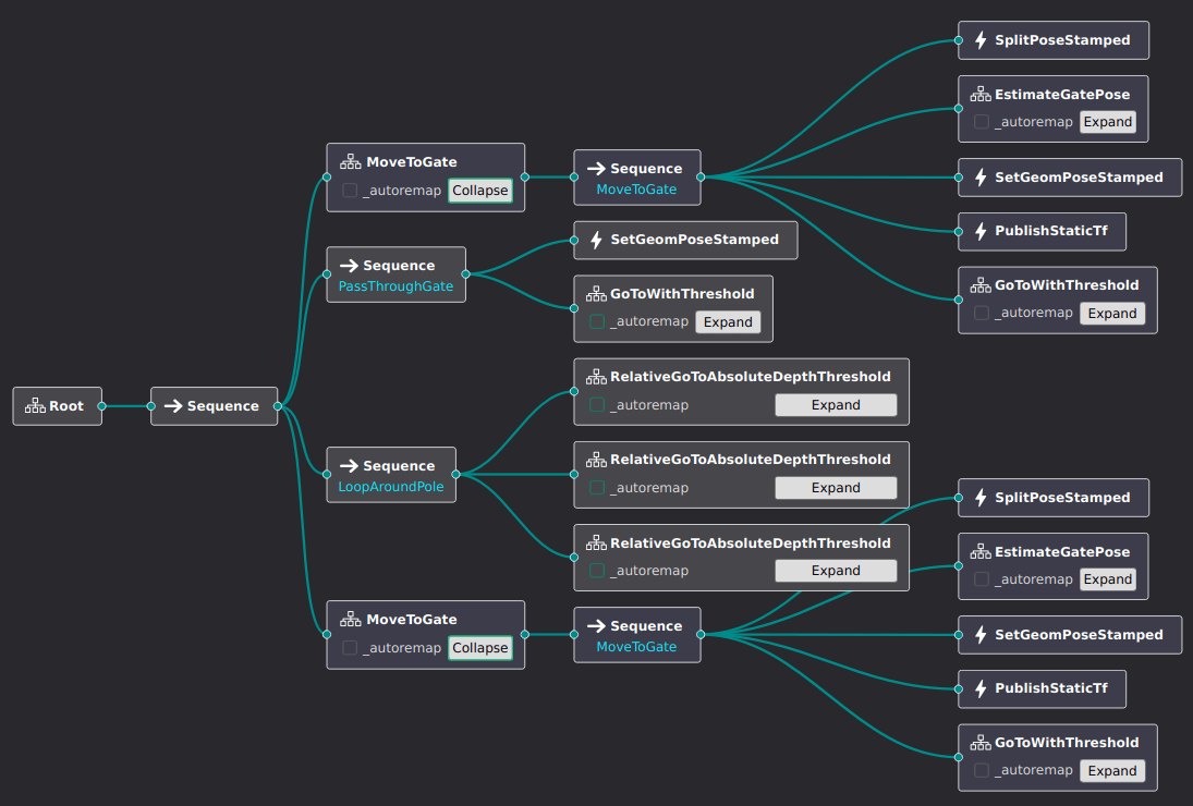
The Behavior Tree (BT) based mission planner that we adopted last year has proven to be highly effective in defining complex behaviours for our vehicle. We have enhanced our mission planner to take advantage of a Graphical User Interface (GUI), which facilitates easy design and modification of mission plans.
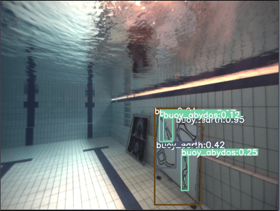
We have upgraded our perception pipeline to leverage the benefits of both deep-learning and traditional computer vision approaches, like YOLOv8 (for object detection and segmentation), Scale-Invariant Feature Transform (SIFT) and Perspective-n-Point (PnP). By combining these two techniques, we aim to enhance the accuracy and robustness of our perception system to improve our chances of localising the different obstacles in the TRANSDEC environment.
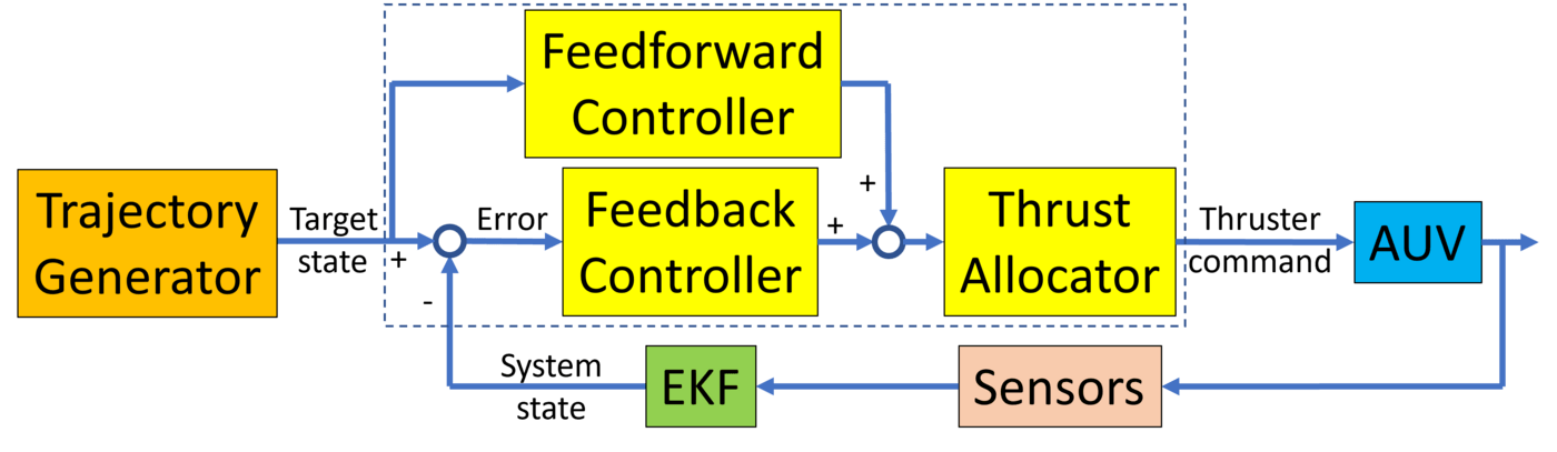
Our battle-tested control system employs a trajectory generator which uses linear segments with polynomic blend to generate smooth continuous paths. These trajectories have limits imposed on the velocity, acceleration and jerk of the vehicle to avoid controller saturation, improving performance for distant setpoint goals.
Competition Strategy
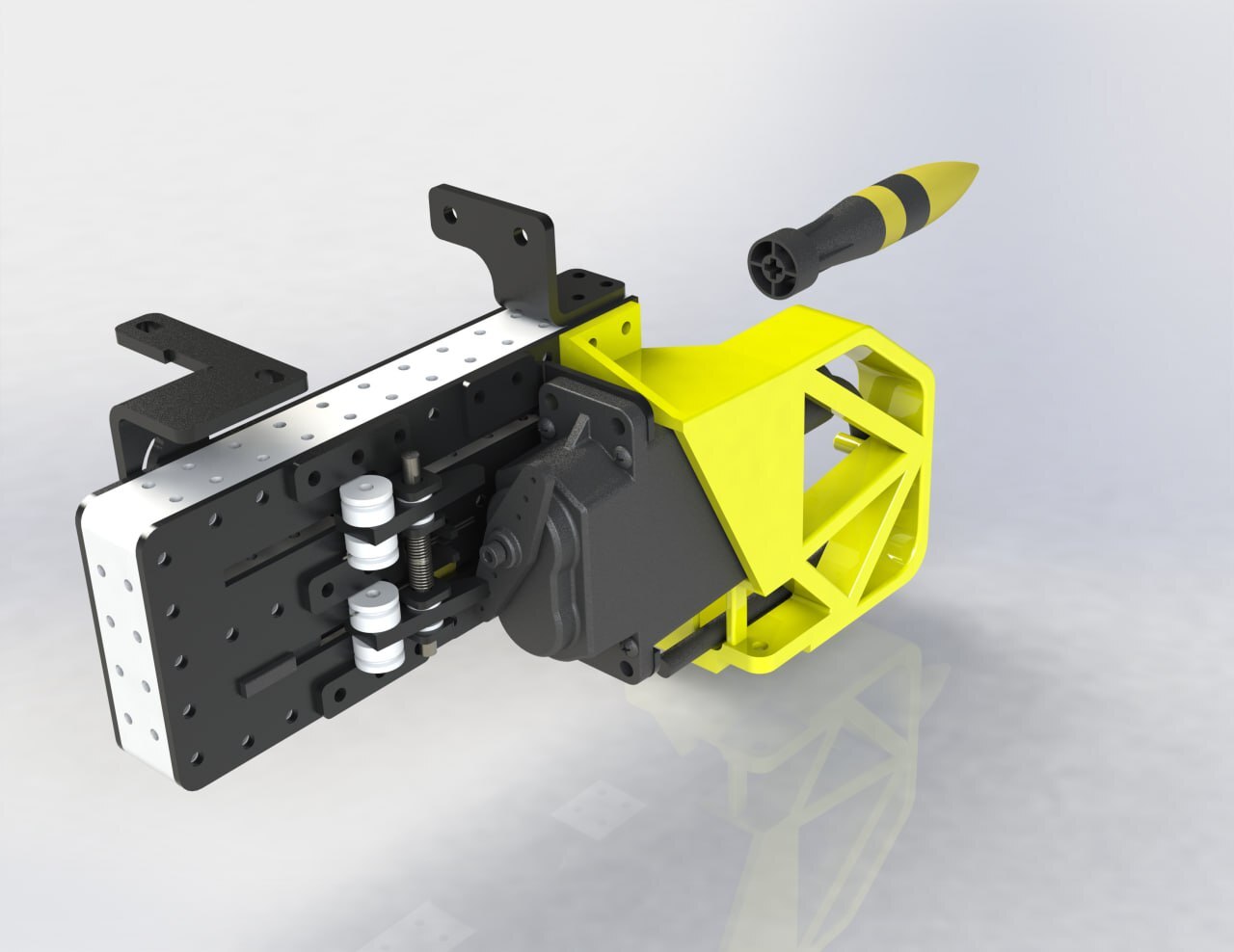
We approach the course using a sensor fusion approach, where we combine readings from various sensors such as our sonar, object detections from machine learning (ML), and acoustic signals from the pingers, to accurately locate and identify objects relevant to the task, such as buoys in the Start Dialing challenge or torpedo openings in the Goa’uld Attack challenge.
Aligning to targets is a significant challenge, requiring a robust control system and accurate estimations for the positions of the target, vehicle, and peripherals such as grabbers and torpedo launchers. Previously, we achieved this by combining ML object detection results with 3D computer vision techniques, such as homography estimation. This year, we have expanded on our use of computer vision to enable even faster and more accurate alignments.
To better ascertain vehicle position, our Inertial Measurement Unit (IMU) has been upgraded to enable our localization pipeline to give more accurate readings. For knowledge of the externally mounted peripherals such as the actuation modules, our vehicle’s Unified Robotics Description Format (URDF) was extensively used to model the relationships in position and orientation between different parts of our vehicle. This allows for much better delivery of autonomy compared to previous years, especially with regard to aligning to obstacles.
For more details, read our technical paper.