The electrical architecture of AUV 4.1 is centered around implementing quality of life changes into the system and electrical workflow improvements.
Improvements also include upgrades to our Operator Control System (OCS) which now supports 4G modem as well as enhanced Wi-Fi connectivity, improvements to power and communication lines and improved visibility of the LED configuration.
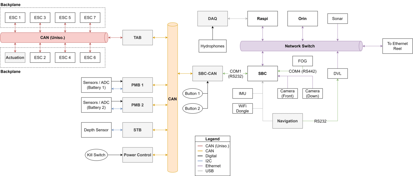
Ethernet and CAN are our primary methods of communication for high and low-level components respectively, allowing for ease of adding new peripherals.
Navigation System
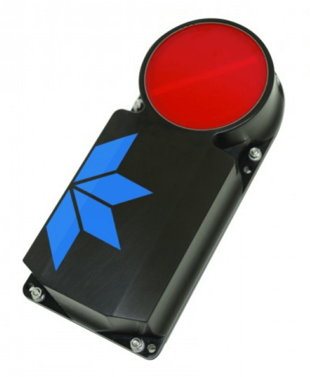
The navigation system on board the Bumblebee AUV 4.1 consists of an Inertial Measurement System (IMU), a Doppler Velocity Log (DVL), and a depth sensor.
The IMU provides critical inertial data at a rapid rate of 100 Hz. The IMU’s proprietary algorithms ensure the correct output data despite the presence of extensive electromagnetic interference generated by the electronics and thrusters.
To improve our navigation system, the team has benchmarked various IMUs. The IMUs provide important odometry data for the vehicle which is the integrated into our control system. In previous years, we found that the IMU was highly susceptible to external magnetic interference. A test mount was printed to allow for testing of several IMUs at the same time under the same conditions.
The DVL is an active sonar system that helps to track the velocity of the AUV via a four-beam solution directed at 30 degrees nominal from the sensor’s ceramic head. The velocity readings obtained are combined with tilt and altitude measurements, and are then resolved into the three orthogonal x, y and z-axes via a least squares fit solution. These resolved readings are further filtered through a direct three degrees-of-freedom Kalman filter, which serves to attenuate noise. These calculations ensures that thee positional coordinates of the vehicle are highly accurate.
Computer System
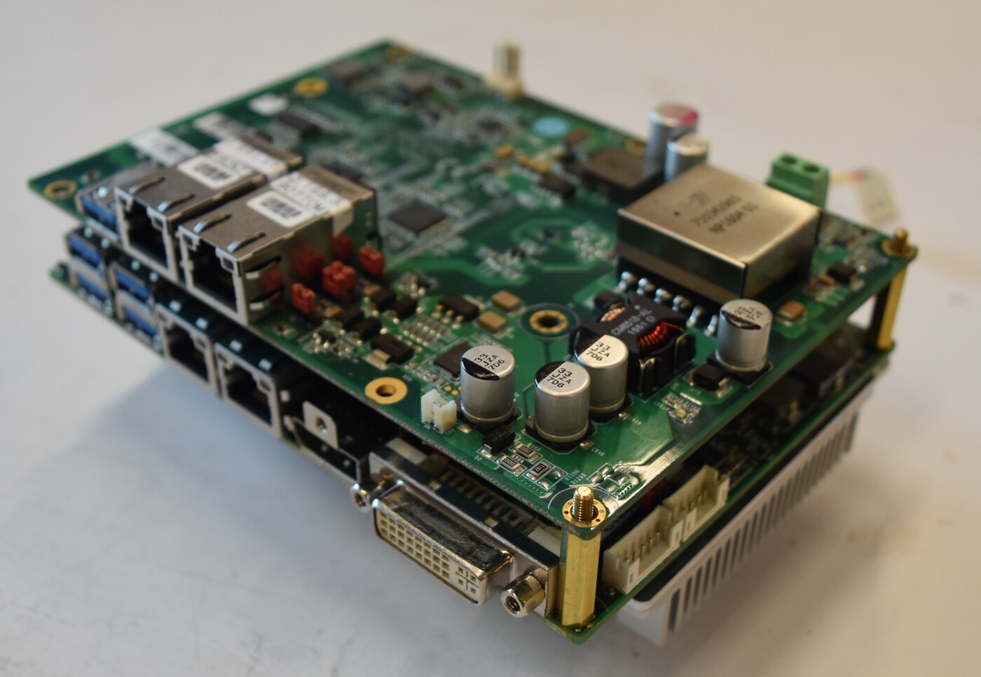
Bumblebee’s computer system is powered by an Intel Core i7-1185GRE quad core processor on an Avalue EGM-TGU Single Board Computer (SBC), along with a 512 GB M.2SATA3 Solid State Drive (SSD). Machine learning tasks are powered by a Nvidia Jetson AGX Orin. The unreliable USB-FTDI circuitry was swapped with RS232 for the SBC to transmit and receive data with the CAN bus. To save space in the hull, we power our 2 Blackfly S PoE Cameras separately instead of using the Power of Ethernet (POE) expansion daughter board.
The computer is connected to the dockside Operator Control Station (OCS) through a 1 Gbps Ethernet tether. Our OCS now supports 4G modem as well as enhanced Wi-Fi connectivity. An in-built screen allows the user to monitor critical vehicle statistics. Furthermore, we have modified our SBC-CAN board which is now able to broadcast telemetry data over UDP.
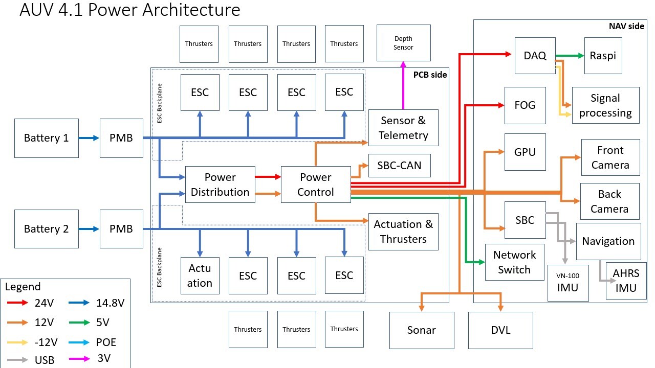
Power Management
The vehicle is powered by two 15000 mAh lithium polymer (LiPo) batteries in parallel, providing approximately two and a half hours of operational time before requiring a recharge. Each LiPo battery is installed into a battery pod with Subconn connectors which allows for both charging and discharging without having to remove the physical battery. The load balancer circuit on the Backplane enables hot swap capability, making the swapping process a smooth one without having to power down the system. Within the pods, the batteries are connected to custom a Power Monitoring Board (PMB) which monitors vital status such as current draw, cell voltage and capacity. The PMB has been upgraded to include a more accurate and space saving current monitoring IC and a PMOS with a higher current rating and larger footprint to improve heat dissipation.
Acoustics
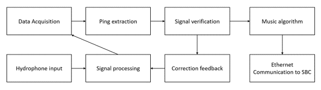
Bumblebee’s acoustic sub-system has four Teledyne hydrophones in a square array, integrated with custom fabricated analog and digital boards. The high-resolution MUSIC (MUltiple SIgnal Classification) algorithm is used for localising the acoustic pinger.
Controller Area Network (CAN)
The CAN protocol is implemented for communication between various devices in the AUV. It is deployed on all the daughter boards, the PMBs and the SBC. The deployment of CAN eliminates single point of failure from our systems by not requiring the SBC to be in the center of the communication loop. With CAN, hardware devices are able to exchange data in a peer to peer fashion over a robust differential CAN bus without additional wiring overheads between devices.
